
Airfoils are generally thickest somewhere around the middle. The classic NACA four-digit airfoils are thickest at 30% of the chord, and laminar flow airfoils are thicker around the 50% mark. Let’s throw out the received wisdom and make some airfoils that are thickest close to the front.
Rather than working with a lifting body, let’s just try to streamline a cylinder by adding a tail.
Well, it’s not quite as simple as that. If there are sharp discontinuities in the curvature of the surface, XFOIL won’t converge. So let’s define the curvature to be constant for the first quarter-circle, then linearly increase it until the trailing edge. Generating the surface takes some numerical integration, as well as iteration to make sure that the trailing edge thickness is zero. Luckily, computers are quite good at iteration. Here are the resulting airfoils:

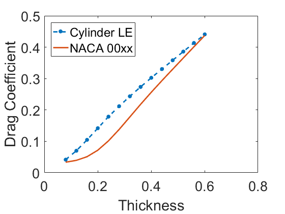
Those look roughly like airfoils. Not perfect, but a decent starting point. Ok, let’s throw them at XFOIL and see what the resulting drag is, at Reynolds numbers of 1e4 and 1e6.
At a Reynolds number of 1e4 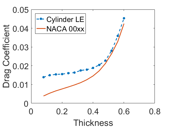
At a Reynolds number of 1e6
At the lower Reynolds number, it isn’t a huge difference: at most a doubling of the drag with the circle-tipped airfoils. At the higher Reynolds number, the new airfoils are few times draggier than the typical NACA airfoils.
One application of these not-great airfoils would be as fairings for wires. Would adding tails reduce the drag force? We need to compare properly. Define \tau as the thickness scaled by the chord length: t/c. The drag force on the airfoil is F_a = \rho U^2 c C_{d,a}/2, and on the cylinder is F_c = \rho U^2 t C_{d,c}/2. The Reynolds number for the cylinder is proportional to the airfoil’s Reynolds number Re_{c} = Re_{a} \tau. The following plots show the dimensionless drag of the different bodies: F/(c \rho U^2/2)
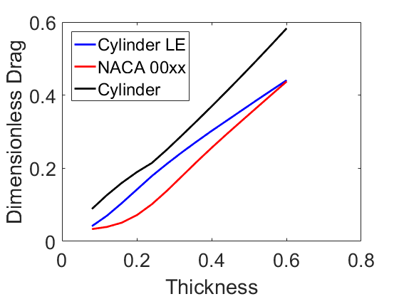
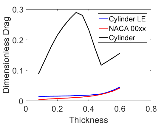
At low speed, the fairings aren’t very useful. At high speed, they are very useful! At these speeds, it makes sense to streamline your wires, even with poorly considered tails!
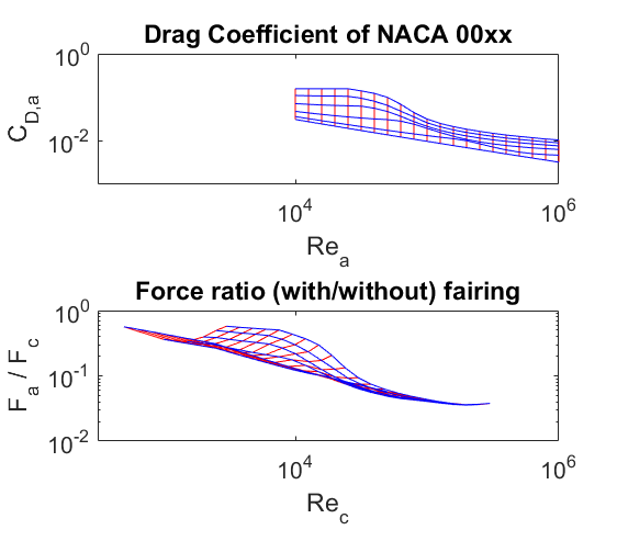
When does it make sense to add fairings to cylinders, more generally? The previous plots weren’t quite a fair comparison, as they are based on the airfoil Reynolds numbers. The next plots should help to decide. The top plot shows the drag coefficients for the fairings (assumed to be symmetric NACA airfoils). The drag coefficient decreases at higher Reynolds numbers, or with thinner airfoils. The blue lines are constant-thickness lines, and red lines are constant-Reynolds number. These carry over to the bottom plot, which shows the drag decrease that occurs when using fairings, as a function of the cylinder Reynolds number. The smaller the plotted value, the more the drag is reduced.
The next question: what is the best fairing length for a given Reynolds number? It suggests using airfoils with thicknesses of around 10% – 20%. For this limited range of Reynolds numbers, it does make a difference: a poor choice could increase drag by 70%. More simulations would be needed to really nail down these numbers.
In summary, slap a tail on that cylinder.