Have you ever played with polarized films? If they’re aligned, they look transparent. If they-re misaligned by 90 degrees, they become opaque. Let’s use this to make pictures!
The intensity of transmission is governed by Malus’s Law, which says that the intensity is cos(\Delta\theta)^2, where \Delta\theta=\theta_1-\theta_2 is the misalignment of the two films. Now how can we use this to make images?
Forone image, with brightness I_1(x,y), it’s easy. Have one film with a constant orientation, \theta_2=0, then \theta_1=\arccos(\sqrt{I_1}). But that’s boring.
What about multiple layers? Let’s say that we make the first image by overlapping the films normally, and the second by rotating film 2 by 180 degrees. The brightness of the new images, J, is
\begin{aligned} J_1(x,y) &= \cos\left[ \theta_1(x,y)- \theta_2(x,y) \right]^2 \\ J_2(x,y) &= \cos\left[ \theta_1(x,y)-\left( \theta_2(-x,-y)-\pi \right) \right]^2 \\ &= \cos\left[ \theta_1(x,y)-\theta_2(-x,-y)\right]^2 \end{aligned}
The rotation means that points are paired in an important way: the brightness at points (x,y) and (-x,-y) depend on the film orientations at both points. So the problem can be independently solved for every pair of rotation-linked points.
Unfortunately, it isn’t easy to get simple analytic solutions. So let’s do some optimization. Define an error function
\epsilon = \sum_{x,y}\left[ (I_1-J_1)^2+(I_2-J_2)^2 \right] ,
and throw random search at it. That works really well for finding a rough approximation, then gradient descent can fine-tune it.
Alternatively, you can find the rough approximation by noticing that you can divide the problem into sections. Say A is the left side, and B is the right side. Since the images are generated as differences, you can set one region to zero and only optimize the rest, like \theta_2(B)=0. Then you can create a 3D grid of each possible \Theta =[\theta_1(A), \theta_1(B), \theta_2(A)] and find the resulting values of J_A(\Theta),J_B(\Theta). With these, you can pick a good starting point for gradient descent for each rotation-pair.
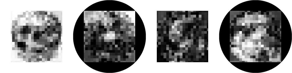
Check out the result with the Mona Lisa and Girl with a Pearl Earring. First, here’s a a rough version that shows the individual squares. They are mounted on circular backings of constant orientation, and are placed atop a background field that’s misaligned by 17 degrees, just to show their outlines.

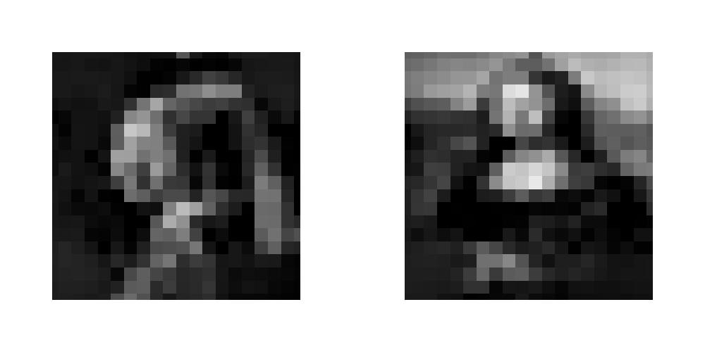
It works! What about higher resolution? The following image shows the original image, recreation, and ten times the absolute difference between the two. You can see that there are some inexact regions, but it does a good job generally!

Using two images is good, but why not four? Apply the same general thought process, and it still works! The image quality is substantially worse, but it does seem to work.

It’ll be easier to tell what these are with higher resolution:
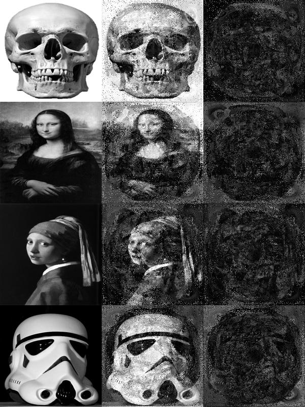
Yep, large error, but now recognizable. I’m impressed that four images can be hidden this way!
How would we build one of these in reality? One option is to buy some films, and cut squares out of them at different angles, then glue them onto some transparent backings. That’s tedious, but feasible. To reduce the tedium, the number of different angles should be limited, which will further reduce the image quality. Another option is to encourage the optimization to give regions of uniform orientation, so that large patches can be cut at the same time.
Further things to think about!